
leave a message
If you are interested in our products and want to know more details,please leave a message here,we will reply you as soon as we can.


Executive Summary: From DFM optimization to mass production, Yistar Plastic delivered a turnkey injection molding solution for a push-button LED lamp targeting the North American and European markets — helping the client cut their time-to-market by 4 weeks.
Client Type
● : North American smart-home brand
Application
● : Motion-sensing LED night light for bedrooms and hallways
Annual Volume
● : 500,000 units in Year 1, projected to double in Year 2
Target Markets
● : United States, Canada, European Union
The product is a minimalist push-button LED lamp — the entire light body consists of a single circular housing with an integrated button module. Users press the top surface to toggle power and adjust brightness. The design demanded three things:
Flawless aesthetics
● : The housing is the product's A-surface, directly facing the consumer. No sink marks, weld lines, or flow marks are acceptable.
Consistent tactile feedback
● : Every press must deliver identical travel distance and damping resistance.
Long-term durability
● : The button mechanism must survive 200,000+ press cycles.
Yistar's Role: When the client approached us, they had already completed industrial design (ID), but faced a critical problem — the original design was not injection-molding-friendly. Multiple prototype rounds showed persistent sink marks, warpage, and button sticking. Our task was to intervene at the DFM (Design for Manufacturing) stage and ensure the design was both manufacturable and cost-controlled at scale.
What appeared to be a "simple round housing" actually involved three interlocking engineering challenges:
|
Challenge |
Specific Issue |
Impact |
|
Wall thickness variation |
Top surface (button area) at 2.5mm, side walls at only 1.2mm; transition zone highly prone to sink marks |
Surface quality failure |
|
Button mechanism precision |
Four internal snap-fit clusters and guide rails, requiring ±0.03mm tolerance |
Inconsistent tactile feel, poor batch uniformity |
|
High-gloss surface finish |
Client required piano-black high-gloss; any microscopic defect would be magnified |
Yield rate under severe pressure |
|
Multi-material assembly |
Housing (PC), button bracket (POM), and light guide (PMMA) must mate within a single assembly |
Complex post-assembly functional validation |
Within the first week of receiving the client's 3D files, we delivered a comprehensive DFM report with three critical design changes:
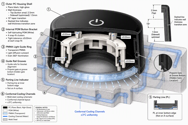
1. Graduated wall thickness transition: Replaced the original sharp 90° transition from top to sidewall with a 15° gradual taper. Simultaneously, locally thickened the sidewall to 1.5mm without affecting the external appearance. This allowed smoother melt flow and eliminated sink marks at the root cause.
2. Parting line relocation: The original design placed the parting line at the top edge of the housing — catastrophic for a high-gloss surface. We moved it to the inner bottom edge, preserving A-surface integrity and finish quality.
3. Gate position optimization: Adopted a pinpoint gate with inverted mold structure, hiding the gate mark inside the button guide-rail groove on the inner surface. The client received finished parts requiring zero secondary gate-trimming operations.
|
Mold Specification |
Detail |
|
Cavities |
1 × 4 |
|
Mold Steel |
S136 ESR mirror-grade steel (HRC 48–52) |
|
Surface Finish |
A1-grade mirror polish (Ra ≤ 0.025 μm) |
|
Cooling System |
Conformal cooling channels + beryllium-copper inserts |
|
Ejection System |
Stripper plate + two-stage ejection |
|
Tool Life |
1,000,000 shots |
Key design decisions:
● Conformal cooling: Given the uneven wall thickness, we integrated 3D-printed conformal cooling channels into the mold. Cavity surface temperature variation was held within ±3°C. Compared to conventional straight-line cooling, cycle time was reduced by 25%, and warpage caused by uneven cooling was effectively eliminated.
● Slider + lifter combination demolding: The internal snap-fit features used 6 sets of lifters; the guide-rail grooves used tunnel sliders — ensuring zero-damage demolding on every cycle.
After tri-party validation with the client and material suppliers, the final material combination:
|
Component |
Material |
Grade |
Rationale |
|
Housing |
PC |
SABIC Lexan 943A |
High flow, high clarity (dyeable to gloss black), UL94 V-2; ideal for thin-wall long-flow applications |
|
Button Bracket |
POM |
DuPont Delrin 500P |
Self-lubricating, high rigidity, excellent fatigue resistance; ensures 200K-cycle durability |
|
Light Guide |
PMMA |
Mitsubishi Acrypet VH |
High light transmission (92%), UV-stabilized; resists yellowing over product lifetime |
After three rounds of DOE (Design of Experiments) optimization, we locked in the following production process window:
|
Parameter |
Setpoint |
Notes |
|
Melt Temperature |
280–295°C |
Wide PC processing window, but requires precise control to prevent degradation |
|
Mold Temperature |
90–100°C (thermolator-controlled) |
High mold temperature is the prerequisite for high-gloss finish |
|
Injection Speed |
Multi-stage: slow → fast → slow |
Prevents jetting marks and air entrapment |
|
Holding Pressure |
80–100 MPa, 6s hold time |
Compensates for shrinkage, eliminates sink marks |
|
Cooling Time |
18s (conformal cooling) |
6s reduction vs. conventional cooling |
|
Total Cycle Time |
35s/shot |
Including part removal and insert placement |
We established a complete QC gating structure for this project:
First Article Inspection (FAI)
● : Full dimensional inspection via CMM at every shift startup; production only begins after 100% pass on critical dimensions.
In-Process QC (IPQC)
● : 5-shot sampling every 2 hours, covering appearance, weight, and critical dimensions.
Process Capability Monitoring
● : SPC control applied to the button guide-rail slot width (the most critical mating dimension), with CPK consistently above 1.67.
<td style="width: 33.3400%; padding: 0.0000pt 0.5000pt 0.0000pt 0.5000pt; border-left: 1.0000pt solid #e4e4e7; mso-border-left-alt: 0.0000pt solid #e4e4e7; border-right: 1.0000pt solid #e4e4e7; mso-border-right-alt: 0.0000pt solid #e4e4e7; border-top: none; mso-border-top-alt: 0.0000pt solid #e4e4e7; border-bottom: 1.0000pt solid #e4e4e7; mso-border-bottom-alt: 0.00
|
Inspection Item |
Standard |
Tool / Method |
|
Appearance |
A-surface free of sink marks, weld lines, flow marks, and black spots (≥0.2mm = reject) |
Standard light source visual inspection |