



Overmolding & Insert Molding: Design Rules and Use Cases

Best purchase I’ve made this winter! The color and knitting are exquisite and it’s so comfy! Went from NYC to Miami without ever taking it off. Super cute!!
Two processes solve the same family of problems from opposite directions. Overmolding adds a second material on top of a finished plastic part; insert molding places a metal or plastic component inside the cavity and molds the part around it. Both eliminate assembly steps, both add tooling complexity, and both fail in predictable ways when the design rules are ignored.
The value is easy to state. A soft-touch TPE grip over a rigid ABS housing replaces two parts, a glue line and a screw; a molded-in brass insert replaces a drilled hole, a tapped thread and a torque specification that a subcontractor has to meet. The cost sits in tooling, cycle time and the tight process window that a two-material part demands.
This article sets out how the two processes differ, which material pairs actually bond, the design rules for overmold thickness and insert wall sections, and the failure modes that show up at T1 when a design has been specified as a picture rather than a process.
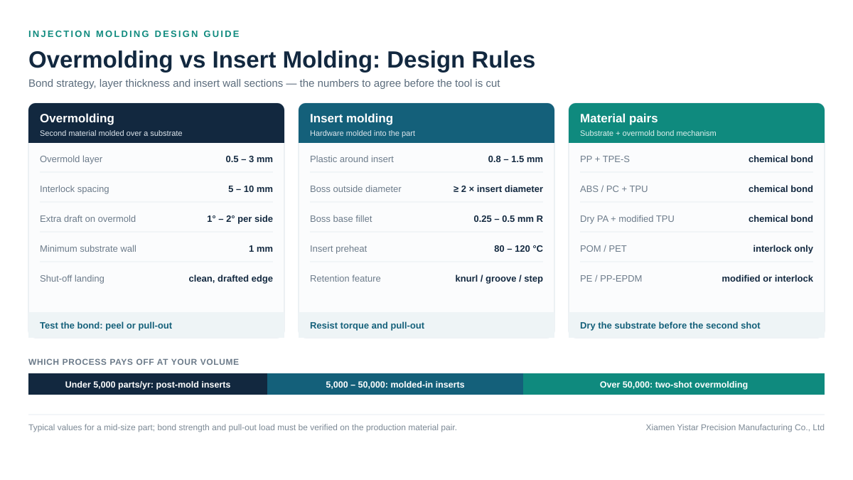
Key Takeaways
- Overmolding molds a second material over a pre-molded substrate, while insert molding molds plastic around a metal or plastic insert placed in the cavity; both are injection molding processes, not assembly operations.
- Overmold layer thickness is typically 0.5 mm to 3 mm; thin layers below 0.5 mm are used for seals and gaskets, and layers above 3 mm add cycle time and sink risk without adding grip.
- Bonding depends on chemistry as much as on design: TPE-S grades bond reliably to polypropylene, TPU grades bond to ABS, PC and PC/ABS, and polyolefin substrates usually need adhesion-modified grades or mechanical interlocks.
- A molded-in insert typically needs 0.8 mm to 1.5 mm of plastic wall around it, with a boss outside diameter at least twice the insert diameter, and knurled or grooved inserts to resist torque and pull-out.
- Post-mold heat-set or ultrasonic inserts are cheaper below roughly 5,000 parts per year, while molded-in inserts win on sealing, load distribution and per-part cost once volume and cycle time allow.
What Is the Difference Between Overmolding and Insert Molding?
Overmolding molds a second material over an existing plastic part to add grip, sealing or colour. Insert molding molds plastic around an insert — usually metal — placed in the cavity. Overmolding creates a two-material part; insert molding creates a single part with embedded hardware. Both are one-shot or two-shot molding processes, not downstream assembly.
The distinction matters most when a drawing reaches a tool shop. An overmolded part is a two-stage process: either the substrate is molded first and loaded into a second tool (insert overmolding), or both materials run in the same machine with a rotating or sliding mold (two-shot molding). An insert-molded part is a single-stage process with an operator or robot loading hardware before each shot, which is why automation and cycle time are the two variables that decide its cost.
| Process | What happens | Typical tooling | Best suited to | Cycle impact |
|---|---|---|---|---|
| Two-shot overmolding | Both materials molded in one machine, mold rotates or slides | One tool, two cavities sets, higher cost | High-volume grips, coloured keys, lens over clear windows | Lowest per-part cost at volume; no handling step |
| Insert overmolding | Substrate pre-molded, loaded into a second tool | Two tools | Soft-touch handles, gaskets on finished bodies | Adds a loading step; substrate must survive the second shot |
| Insert molding | Hardware loaded into the cavity before each shot | One tool plus loading fixture | Threaded inserts, strain relief, sensor housings | Cycle adds manual or robotic loading |
| Post-mold assembly | Heat-set, ultrasonic or press-fit inserts | No extra tooling | Prototypes, low volume, revisions | Adds labour, not machine time |
How Do You Choose a Substrate and Overmold Material Pair?
Choose the pair by bond mechanism first and processing temperature second. TPE-S (SEBS-based) grades bond to polypropylene by co-crystallisation; TPU grades bond to ABS, PC and PC/ABS by polar interaction; polyolefins such as PP and PE generally need an adhesion-modified grade or a mechanical interlock. The overmold material must also be processed below the substrate's softening range.
The second constraint is thermal, and it is the one that produces ugly failures. An overmold shot runs at 180 °C to 230 °C, which is far above the heat deflection temperature of an ABS or PC substrate. The part survives because the melt front traverses the overmold cavity in a fraction of a second and the substrate acts as a heat sink — not because the temperature difference is safe in principle. Thin overmold layers, fast fill and good cooling therefore protect the substrate as much as they protect cycle time.
| Substrate | Recommended overmold | Bond mechanism | Design notes |
|---|---|---|---|
| Polypropylene (PP) | TPE-S (SEBS), adhesion-modified | Co-crystallisation | Best chemical bond of any common pair; no interlock needed if grade is right |
| ABS, PC/ABS | TPU, TPE-S with modified base | Polar interaction | Keep overmold under 2 mm; long, hot shots can sink the substrate surface |
| Polycarbonate (PC) | TPU | Polar interaction | Dry the TPU thoroughly; PC stress-cracks where the melt front impinges |
| PA6, PA66 (dry) | TPU with adhesion modifiers | Polar interaction | Dry the substrate; moisture in PA produces voids at the bond line |
| POM, PET, PBT | Mechanical interlock only | None reliable | Specify dovetails and through-holes instead of relying on adhesion |
| PE, PP-EPDM | TPE-S modified, or interlock | Partial | Surface treatment or interlock if bond strength matters |
What Design Rules Apply to Overmolding?
Keep the overmold layer between 0.5 mm and 3 mm, provide mechanical interlocks every 5 mm to 10 mm along the bond line, and design the shut-off so the two materials meet on a defined edge. Overmold thickness drives bond area, grip feel and cooling time at once, which is why it is the first number to agree in a design review.
- Layer thickness. 0.5 mm to 1.5 mm suits grips and tactile surfaces; 2 mm to 3 mm suits thick gaskets and impact ends. Above 3 mm, expect sink marks on the substrate and a cycle time penalty that outweighs any functional gain.
- Mechanical interlocks. Through-holes, dovetails and undercuts spaced every 5 mm to 10 mm along the perimeter carry load when adhesion is marginal, and they are the only option when the pair has no chemical bond.
- Shut-off design. The overmold tool must close on a clean, drafted substrate surface. A shut-off landing on a textured wall lets the second material flash along the grain, and the flash cannot be removed without damaging the texture.
- Substrate stiffness. The substrate must carry the second shot without deflecting or melting. Thin walls under 1 mm flex under injection pressure and open the shut-off.
- Draft and ejection. The overmold cavity needs its own draft, commonly 1° to 2° additional per side on soft TPE, and ejection must act on the rigid substrate rather than on the soft layer.
- Colour and finish. The overmold defines the visible surface, so texture grade, gloss level and gate position belong to the second material — not to the substrate underneath it.
What Design Rules Apply to Insert Molding?
Allow 0.8 mm to 1.5 mm of plastic around a molded-in insert, make the boss outside diameter at least twice the insert diameter, and hold insert position with a core pin or pocket rather than with friction. Inserts should be preheated, and every insert should be knurled, grooved or stepped to resist torque and pull-out.
| Design parameter | Typical value | Why it matters |
|---|---|---|
| Plastic wall around insert | 0.8 mm – 1.5 mm | Below 0.8 mm the boss cracks under thermal contraction; above 1.5 mm the boss sinks |
| Boss outside diameter | ≥ 2 × insert diameter | Spreads the load and controls sink at the boss base |
| Boss base fillet | 0.25 mm – 0.5 mm radius | Removes the stress concentration that starts a crack |
| Insert retention feature | Knurl, groove or step | Carries torque and pull-out that friction cannot |
| Insert preheat | 80 °C – 120 °C | Cuts the thermal gradient, reducing residual stress and short shots |
| Rib thickness beside boss | ≤ 0.6 × boss diameter | Prevents a thick-to-thin junction that sinks and warps |
| Molded-in vs post-mold | Volume dependent | Molded-in spreads load and seals; post-mold is cheaper for small runs |
Two decisions get confused here. Molded-in inserts are placed in the cavity before closing, so the tool needs a core pin or a pocket to hold them and the process needs an operator or a robot. Post-mold heat-set or ultrasonic inserts are installed after molding, which keeps cycle time short and lets a generic insert be used across several parts. Molded-in inserts win when the joint has to seal, when the insert carries continuous load, or when part volume justifies the loading automation.
What Failures Do Overmolding and Insert Molding Cause?
The common failures are substrate melt-through, delamination at the bond line, flash at the shut-off, insert rotation or pull-out, and stress cracking around bosses. Almost all of them trace back to processing windows: overmold melt temperature, fill speed, insert preheat and pack pressure. They show up at T1 and are cheap to correct in the process window, expensive to correct in steel.
- Delamination appears as a lifting edge or a whitened bond line in peel testing. Causes include an adhesion-modified grade that was not specified, moisture on the substrate, or a mold release agent that reached the bond surface.
- Substrate melt-through is a sinking or glossy patch where the second shot landed. Shortening the fill, thinning the overmold layer or dropping the melt temperature by 10 °C to 20 °C usually resolves it.
- Flash at the shut-off means the second material found a gap between substrate and tool. The fix is a tighter shut-off, more clamping support under the substrate, or a substrate wall thick enough not to flex.
- Insert rotation and pull-out indicate smooth inserts, insufficient boss wall, or a boss without a fillet. Knurled or stepped inserts and a small increase in boss diameter address both.
- Stress cracking around a boss follows from thermal contraction of the plastic over a rigid insert. Insert preheat and a lower packing pressure reduce it; a thicker boss usually makes it worse.
When Are These Processes Worth the Cost?
Overmolding and insert molding are worth their tooling cost when they replace an assembly step that would otherwise be performed on every part. The break-even is a comparison of tool cost and cycle time against the labour, adhesive, fasteners and rework that the process removes — and it moves with volume, not with part complexity alone.
Where they pay off most clearly:
- Sealing and ingress protection. A molded gasket or overmolded seal removes a separate gasket, an installation step and the risk of a mis-seated seal that fails an IP67 test. Enclosure programs driven by ingress requirements benefit most — the material and sealing side of that decision is covered in our guide to selecting plastic electronic enclosure case kits.
- Grip and tactile feel. Power tools, medical handles and consumer devices use overmolding so the soft surface is part of the part, not an accessory that peels off in service.
- Threaded connections in thin-walled parts. A molded-in brass insert gives a machine screw a load-bearing thread in a housing wall too thin to tap.
- Assembly reduction at volume. Two-shot molding removes a handling step and a second machine cycle, which is why it becomes cheaper than insert overmolding above roughly 50,000 parts a year.
The process side of both materials has to be settled before a two-material tool is cut. Cycle, packing and cooling for the substrate are covered in our guide to the injection molding process, and the geometry that both shots share — draft, gate location and cooling layout — is set out in our guide to mold design fundamentals. Substrate and overmold selection also follows the same shrinkage, melt-flow and filler logic as any single-material part, covered in our guide to choosing the right plastic injection molding material.
At Yistar, Custom Engineering Plastic Components and custom consumer electronics projects are produced with both processes: overmolded grips and gaskets where sealing or tactile feel matters, and insert-molded housings where a thread or a strain-relieving connection has to survive repeated assembly.
FAQ
What is the difference between overmolding and insert molding?
Overmolding molds a second material over a pre-molded plastic part, adding grip, sealing or a second colour. Insert molding molds plastic around a metal or plastic insert placed in the cavity, embedding hardware in a single part. Overmolding produces a two-material part; insert molding produces one material with embedded components.
How thick should an overmold layer be?
An overmold layer is typically 0.5 mm to 3 mm thick. Layers of 0.5 mm to 1.5 mm suit grips and tactile surfaces, and 2 mm to 3 mm suit gaskets and impact ends. Below 0.5 mm the layer is only practical for small seals, and above 3 mm it adds cooling time and sink risk without improving function.
Which materials bond well in overmolding?
TPE-S grades based on SEBS bond reliably to polypropylene, and TPU bonds to ABS, PC and PC/ABS through polar interaction. Polyolefins such as PE and PP-EPDM normally need adhesion-modified grades or mechanical interlocks. POM, PET and PBT have no dependable chemical bond, so those pairs must be designed with dovetails and through-holes.
How much plastic should surround a molded-in insert?
Allow 0.8 mm to 1.5 mm of plastic wall around a molded-in insert, with a boss outside diameter at least twice the insert diameter and a base fillet of 0.25 mm to 0.5 mm. Preheating inserts to 80 °C to 120 °C reduces residual stress. Knurled or grooved inserts are needed wherever the joint must resist torque.
Is it cheaper to mold inserts in or install them after molding?
Above roughly 5,000 parts a year with a stable design, molded-in inserts are usually cheaper per part and distribute load better, because the loading step is automated and the insert is encapsulated. Below that volume, post-mold heat-set or ultrasonic inserts avoid loading fixtures and tooling changes, and they let the same insert be used across several parts.
Conclusion
Overmolding and insert molding both trade tooling complexity for a lower part count and a more reliable joint, and both are decided by numbers that belong on the drawing: overmold layer thickness, interlock spacing, plastic wall around the insert and process temperature relative to the substrate. Agree those four figures before the tool is cut, confirm the material pair by peel or pull-out testing rather than by reputation, and the process window at T1 becomes a tuning exercise instead of a redesign.
Send us your part model with the substrate, the insert or overmold material you have in mind and the load the joint has to carry. We will review the bond strategy, the wall sections and the tooling concept, and quote both processes so you can compare them against assembly.
Contact Us
Xiamen Yistar Precision Manufacturing Co., Ltd
Address: Room 401, No. 37 Huliyuan, Tong'an District, Xiamen, Fujian, China
Phone / WhatsApp: +86-18064076912
Email: info@yistar-plastic.com
Open Hours: 24 Hours
Contact Yistar with your substrate, insert or overmold material and joint requirements for a bonding review, a tooling concept and a quotation for both processes.